Case Studies
1. Lifting Point
A lifting point assembly for a 300‑tonne structure was evaluated to ensure safe offshore installation. The verification considered dynamic amplification (DAF), center of gravity offset, and skew load effects, all of which significantly influence load distribution during lifting.


The structural capacity was checked using the allowable stress method in accordance with ANSI/AISC 360, while offshore compliance requirements were assessed per DNV ST‑N001. The analysis identified areas where load paths and stresses could be improved. The pad eye was verified by hand calculations. Based on the findings, the lifting point design was refined and strengthened to meet installation requirements and achieve full compliance with the selected codes. The final configuration provided a safe, reliable, and code‑compliant solution for offshore lifting operations.
2. MQC Support
A Multi Quick Connector (MQC) support assembly was evaluated to confirm its structural integrity under offshore operational loads. The connector functions as a critical interface between subsea equipment and supporting structures, requiring compliance with NORSOK, Eurocode 3 (EN 1993‑1‑8), and DNV RP‑C208.


Finite Element Analysis was performed in ANSYS, using nonlinear material and contact modelling to capture realistic load behavior. The analysis methodology followed DNV RP‑C208, where acceptable plastic strain limits were taken from the calibration cases provided in the recommended practice. Design and resistance factors were applied in accordance with NORSOK, and weld capacities were verified using Eurocode 3 (EN 1993‑1‑8).
The results confirmed that the MQC support assembly satisfied all strength and deformation requirements. Plastic strain levels remained within the allowable limits defined by DNV RP‑C208, demonstrating full compliance and readiness for service in offshore conditions.
3. Bridge & Stair Structures
A structural assessment was performed for a bridge walkway and a stair walkway, each supported by a rotating turntable. Both structures were analyzed under self‑weight, pedestrian live loads, and wind loads using the load factors defined in the project. Finite element analysis in ANSYS was used to evaluate stress distribution and deformation, and the global response of both walkway structures was found to be within acceptable limits. Cross‑sections at critical locations were verified using the Section Check Tool in accordance with Eurocode 3, 1993 1-1.


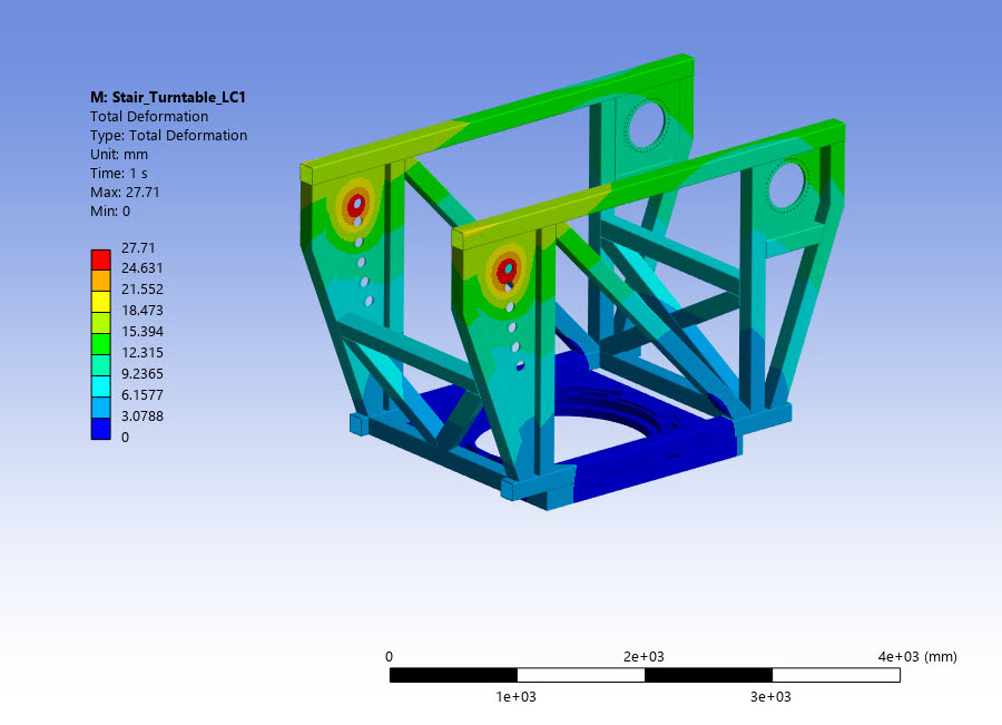

Local analysis of the turntable assemblies, however, revealed overstress conditions. Reinforcement of the beam flanges and the interface plate was recommended, and the assembly was confirmed to be satisfactory after the modifications were implemented.
4. Suction Pile Analysis
A nonlinear buckling assessment was performed to evaluate the structural capacity of suction piles during installation. The analysis incorporated geometric imperfections derived from eigenvalue buckling modes, with magnitudes calculated according to Eurocode 3, EN 1993‑1‑6 fabrication tolerance class B. The suction pile was modelled using shell elements with nonlinear material properties, and soil interaction was represented through nonlinear springs calibrated stiffness data.

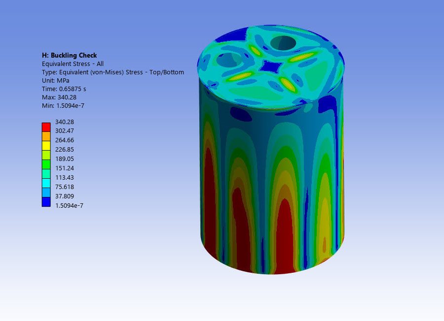
The nonlinear buckling results demonstrated that the suction pile possesses sufficient capacity for installation stages. The allowable suction evaluated was 494 kPa versus a required suction of 280 kPa. Overall, the installation analysis confirmed that the suction pile meets the required structural capacity criteria, with no risk of buckling failure during installation under the evaluated soil conditions and load factors.
5. Limit State Design of a Subsea Steel Structure
A structural code check was performed for a subsea structure with an approximate weight of 200 tons. The assessment covered all relevant load effects generated by the contained subsea equipment, as well as lifting, transport and trawl load conditions defined for the project. The verification was carried out in accordance with NORSOK, Eurocode, and DNV‑ST‑N001, ensuring compliance with recognized offshore design requirements.


Finite element analysis was used to evaluate global behavior, local stresses, and member & Joint capacities under the specified load cases. The structure was checked for strength, stability, and utilization against the governing code limits.
The results demonstrated that the structure satisfies the applicable code requirements, with all critical sections remaining within allowable utilization levels for the defined operational and lifting scenarios.
6. DOP Analysis
A subsea protection structure was assessed for dropped‑object impact loads in accordance with NORSOK U‑001. The analysis considered two representative impact scenarios defined by the project:
- a 50 kJ impact from a 700 mm diameter object, and
- a 5 kJ impact from a 100 mm diameter object.
These cases represent typical accidental loads associated with handling operations, tool deployment, and potential equipment drops during offshore intervention activities.

Finite element analysis was used to evaluate the structural response under both impact energies. The assessment focused on local deformation, stress levels, and the ability of the structure to absorb impact energy without compromising its protective function. Material nonlinearity, contact behavior, and realistic boundary conditions were included to capture the transient nature of the event.
The results confirmed that the protection structure maintains adequate integrity under both dropped‑object scenarios. No critical plastic deformation or failure mechanisms were observed, and the structure satisfies the acceptance criteria defined in NORSOK U‑001 for accidental impact loads.
7. HISC Assessment of Super Duplex
A Hydrogen Induced Stress Cracking (HISC) assessment was performed for a set of super duplex piping components present in the subsea environment. The evaluation followed the methodology of DNVGL‑RP‑F112, using material properties, acceptance criteria, and strain limits applicable to duplex components exposed to cathodic protection.
Category 2 assessment was applied to the complex piping components, while the weld was checked using Category 1 criteria. The models included internal pressure (14.3 MPa), thermal gradients, and external loads. Nonlinear material behavior was incorporated to capture strain development under combined loading.


The results demonstrated that all components satisfied the HISC acceptance criteria. Membrane and peak strains remained below the allowable limits defined in DNVGL‑RP‑F112. Weld checks also met the Category 1 stress requirements.
Overall, the assessment confirmed that the super duplex piping system maintains adequate resistance to HISC under the governing operational loads, temperature conditions, and cathodic protection environment.
8. Flange Connection Check
A detailed finite element assessment was performed to verify the structural integrity of a flange connection subjected to combined operational loads. The analysis considered internal pressure, thermal gradients, and external loads transferred through the connected piping system.
A refined 3D finite element model of the flange assembly was developed, including bolt pretension, gasket contact, and realistic boundary conditions. Loading and boundary conditions were applied as required by the project.


The results demonstrated that the flange connection maintained acceptable stress and deformation levels across all evaluated load cases. Local stresses in the flange neck and bolt region remained within allowable limits defined by the governing offshore design codes. The assessment confirmed that the flange provides sufficient capacity for the operational envelope and does not exhibit any risk of overstress or structural instability.